
— 2026 technical guide · Installing the central units
Installing the central units.
S100 to S400 + S500.
Real diagrams. Clear steps. No improvised connections.
Wall mounting, network connection, muffler, power supply and low-voltage control, commissioning. From S100 to S400, plus the specific series-mounting configuration for the S500 (main body + booster).
— Before you start
Real diagrams. Clear steps.
This guide covers the installation of AspiWall S100 to S400 central units (wall mounting, network connection, air inlet, muffler, power supply and low-voltage control, commissioning), then the specific configuration of the S500 — main body + booster. 50.8 mm Ø PVC vacuum piping network.
Air connections, power supply and bag or filter maintenance vary by model. Keep the specific manual supplied with the central unit.
— Contents
From location to commissioning.
Then the S500 series-mounting.
Choose and prepare the installation area
A dry, ventilated room, accessible for servicing.
Mount the central unit and connect the PVC
The central unit is carried by the wall, never by the PVC.
Move the air inlet from left to right
For the S200, S300 and S400.
Mount the muffler correctly
Air outlet always kept clear.
Power supply and control
230 V + low-voltage control.
Test before finishing
A methodical check immediately reveals any fault.
The S500: main body + booster
A specific architecture, different from the S100 to S400.
Follow the dimensions for both mounts
Layout dimensions for the series configuration.
Connect the main body and the booster
Linking the modules, in series.
Finalize the S500
220/240 V - 15 A power supply and control.
Installer checklist
An installation that stays removable, accessible and logical to maintain.
— The essentials
The 4 rules for
a reliable installation.
The central unit is carried by the wall, never by the PVC.
The last connection to the central unit stays removable (sleeve + clamps).
Every unused air inlet is capped.
The muffler outlet always stays clear.
Choose and prepare the installation area
A dry, ventilated room, accessible for servicing.
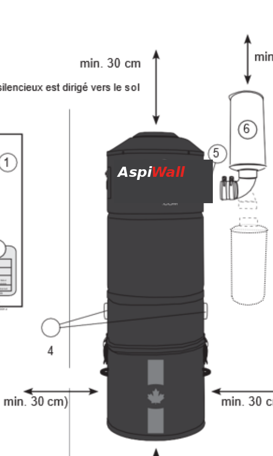
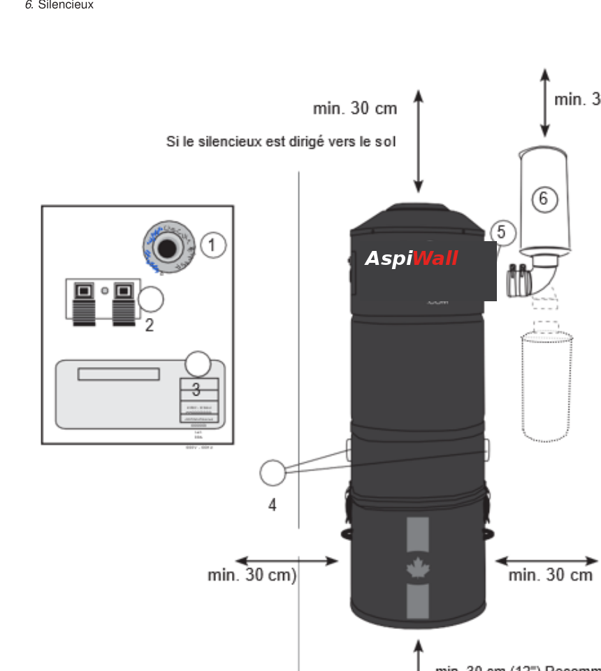
Install the central unit in a dry, ventilated room that is accessible for servicing: garage, basement or utility room.
Clearance
Around the central unit for servicing and ventilation.
Below the canister
Recommended below the canister for removal and maintenance.
Power outlet
Between the central unit and the dedicated power outlet.
Location
Not outdoors, and not in an area exposed to water.
A narrow, unventilated cabinet makes servicing harder and can hinder cooling and air exhaust.
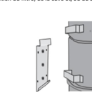
Hold the central unit in place, open the canister latches and check that the bag, canister and filters remain accessible without dismantling the network. Have a level, drill and suitable fixings ready; the mounting plate is supplied.
Mount the central unit and connect the PVC
The central unit is carried by the wall, never by the PVC.
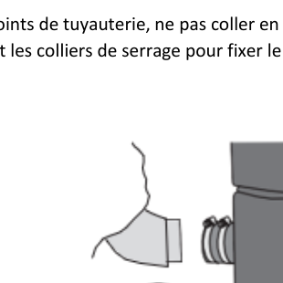
The other network connections are assembled according to the system used. The immediate connection to the central unit remains removable for servicing.
Cut cleanly, deburr each pipe and check alignment before gluing. An unused air inlet must always be capped with the supplied plug.
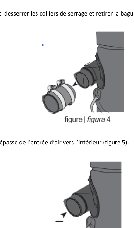
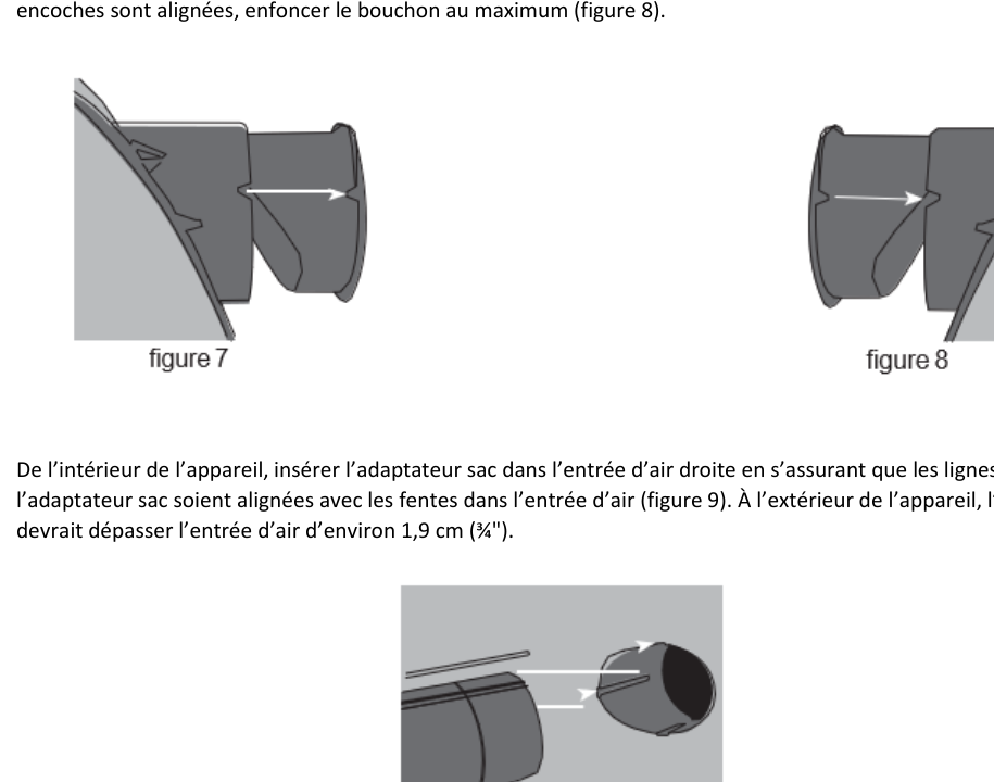
Move the air inlet from left to right
For the S200, S300 and S400.
The procedure below applies only to the S200, S300 and S400. The S100 does not follow this inlet change (do not force the internal adapter). Nor does the S500: it has a single air inlet, on the left.
Mount the muffler correctly
Air outlet always kept clear.
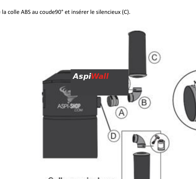
Never block the muffler outlet. If it points downward, keep at least 30 cm clear below its outlet.
Hold the muffler in place before final gluing to check it does not obstruct canister removal or wall access.
Markers: A — sleeve · B — 90° elbow · C — muffler · D — air outlet.
Power supply and control
230 V + low-voltage control.
Power supply
Provide an outlet within 1 m, with earth, on a dedicated circuit. For the S100 to S400 models covered by the manual: 220/240 V - 10 A. No extension cord and no modification of the power cord.
The outlet, earthing and protection must comply with the RGIE (Belgian electrical code). If in doubt, have a qualified electrician carry out the work.
Low-voltage control
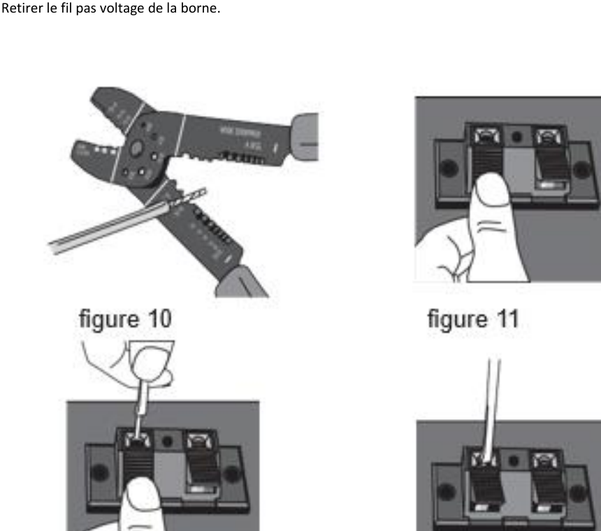
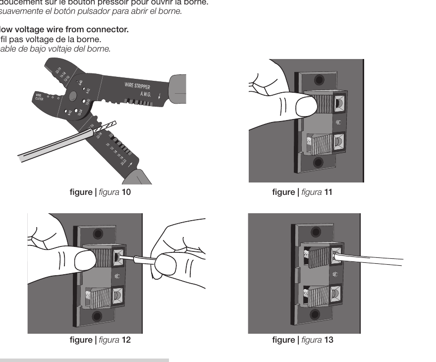
On the S100 to S400, strip about 0.5 cm of each conductor. Press the push-button, insert the wire, then release. Repeat for the second terminal.
Quick test
- 230 V connection complete.
- Two low-voltage conductors inserted.
- Earth checked.
- Each inlet triggers the central unit.
Test before finishing
A methodical check immediately reveals any fault.
A methodical check makes it possible to immediately detect a leak, an uncapped inlet or a poorly connected control.
Final check
- Central unit firmly engaged in its mounting plate.
- Last connection removable and airtight.
- Muffler installed and outlet clear.
- Low-voltage control correctly connected.
- Consistent suction across the various points of the network.
- Canister aligned and latches closed.
- Unused inlet capped.
- Power supply compliant and earth present.
- All inlets trigger the central unit.
- No abnormal whistling around the accessible connections.
Test several inlets and let the central unit run for a few minutes. Check that startup is stable and there is no abnormal mechanical noise.
A large difference between two areas may indicate a leak, a poorly closed inlet or a blockage.
Do not vacuum water, hot ashes or plaster dust during commissioning.
The S500: main body + booster
A specific architecture, different from the S100 to S400.
The S500 is different from the S100 to S400. It consists of a main body with canister and a secondary motor unit — the booster.
Receives the vacuum network on its single air inlet (on the left), holds the canister and filtration.
Secondary motor unit mounted beside and above the main body according to the mounting dimensions.
For the AspiWall S500, follow only the configuration presented in the following sections.
Two wall mounts, space for the metal link between the modules, the muffler, and access to the canister.
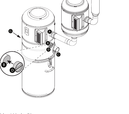
Follow the dimensions for both mounts
Layout dimensions for the series configuration.
The original diagram gives the layout dimensions for the series configuration of the machine corresponding to the AspiWall S500. Mark them on the wall before fixing the mounts.
| Marker | Dimension |
|---|---|
| Main mount height | 154.94 cm |
| Booster mount height | 208.28 cm |
| Vertical gap between mounts | 58.10 cm |
| Horizontal offset | 43.18 cm |
Mark the axes, check the level, then hold the modules and the link in place before permanently tightening the mounts.
Keep 30 cm clear around the working areas and 40 cm recommended below the main body's canister.
Connect the main body and the booster
Linking the modules, in series.
On the AspiWall S500 in series, there is nothing to cap: a single air inlet (on the left) feeds the main body, and its air outlet runs to the booster. No right inlet and no parallel outlet to plug.
When the S500 is running, the metal air-outlet ducts can become very hot. Avoid any contact with heat-sensitive materials and keep service access clear.
Finalize the S500
220/240 V - 15 A power supply and control.
S500 power supply — 220/240 V - 15 A
The manual for the machine corresponding to the S500 specifies a dedicated electrical circuit with earthing and 15 A protection for this model.
The central unit must be connected to a suitable outlet, with earth, without modifying the power cord.
Low-voltage control — on / off
Strip about 1 cm, open the terminal with the push-button, insert the conductor, then release. Repeat for the second terminal.
Test each inlet, let the whole system run for a few minutes and check the stability of the main body and booster.
Installer checklist
An installation that stays removable, accessible and logical to maintain.
S100 to S400
- Solid wall mount and central unit correctly engaged.
- Service clearances maintained.
- Last connection not glued to the central unit.
- Unused inlet capped.
- Canister and bag correctly installed.
- Muffler outlet clear.
- 220/240 V, dedicated circuit, earth, no extension cord.
- Low-voltage control tested on all inlets.
S500
- Main body and booster fixed according to the series dimensions.
- Air inlet (on the left) connected to the main body.
- Link from the main body to the booster complete.
- Booster muffler outlet clear.
- Power supply compliant with the intended circuit.
- Low-voltage control connected.
- Full test of the whole system carried out.
A clean installation should stay removable, accessible and logical to maintain. If in doubt before final gluing, take photos of the whole setup and contact AspiWall before closing the network.
— View online
The complete guide, on screen.
Browse all 12 pages directly in your browser, or download the PDF to take on site.
Document not displaying? Open the guide in a new tab.
— Download
Everything you need to install.
Installation guide for AspiWall S100 to S400 and S500 central units: location, mounting, PVC connection, air inlet, muffler, 230 V power supply, low-voltage control, commissioning and S500 series mounting. Document in French.
Need some support?
AspiWall can help you install a central unit, check an installation or troubleshoot a central vacuum system.