
— Installation guide · 2026 technical edition
Traditional network.
Wall, floor and kitchen inlets.
A well-planned network is decided before the first glue joint. The complete installation guide, compatible with AspiWall & Husky.
Design and installation of a traditional 50.8 mm PVC vacuum network, with wall inlets, floor inlets and a kitchen/toe-kick inlet. From layout to final test — the whole guide is below.
— Before you start
The right network is decided before the first glue joint.
This guide covers the design and installation of a traditional 50.8 mm PVC vacuum network, with wall inlets, floor inlets and a kitchen/toe-kick inlet. It follows the principles of the supplied Husky manual and presents them within the AspiWall range.
The principle
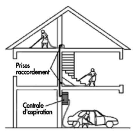
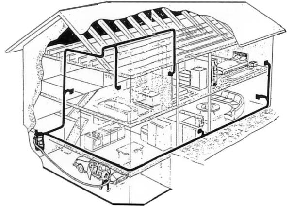
The central unit is installed in a garage, basement, laundry room or a dry, accessible technical room. The inlets are connected to the central unit by an airtight PVC network. A 24 V low-voltage control wire connects the inlets to the central unit.
Start-up happens either when the hose is inserted or via the handle switch, depending on the hose and inlet used.
Air connections, any exhaust venting, power supply and filter or bag maintenance vary by central unit model. Always keep the specific manual for the central unit.
A network for a retractable hose requires specific rules for storage length, bend radius, fitting direction and inlet configuration. Do not size a retractable network using this document.
— Contents
A job-site journey.
From layout to final test.
Prepare the installation
Locate, measure, check — only then drill.
Position the traditional inlets
Actual coverage matters more than the number of inlets.
Choose the network routing
Adapt the installation to the construction type.
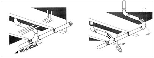
Route the network
A direct main line, short branches.
Choose the fittings and the right direction
Matching diameter is not enough — geometry matters.
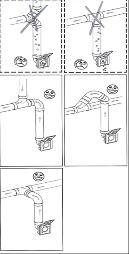
Avoid gravity drops
A poorly connected downward branch can fill up with no suction.
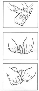
Cut, prepare and glue
Airtightness is won through preparation, not glue quantity.
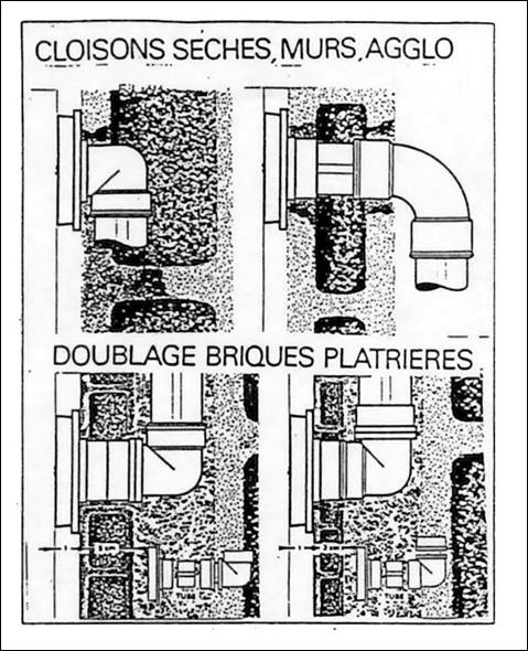
Install the back-boxes
The finished position must be planned before plastering.
Wire the 24 V low-voltage control
All inlets are wired in parallel.
Fit the wall and floor inlets
Connect without gluing the inlet itself.
Install the kitchen / toe-kick inlet
Sweep crumbs toward the inlet and trigger it with your foot.
Mount the central unit
Accessible for maintenance, away from living areas.
Connect and commission
Test every inlet before considering the job finished.
Use and maintain
The network lasts, provided the central unit's limits are respected.
Diagnose and inspect
Start with the simple causes, then isolate the area.
— The essentials
The 4 rules that prevent
most problems.
Short 90° elbow only behind an inlet.
T/Y fittings are oriented in the direction of suction.
Square cut, deburring and chamfering before gluing.
No inaccessible low-voltage electrical connection.
Prepare the installation
Locate, measure, check — only then drill.
Before any drilling, draw up a simple plan and check the actual routes available through the building. The goal is not to draw a network that looks "nice" on paper, but to keep a short, direct and accessible path wherever possible.
Plan the inlets
Identify coverage areas and check the hose's actual reach around furniture.
Identify obstacles
Load-bearing walls, beams, ducts, screeds, hollow-core floor blocks, technical conduits and cut-outs.
Locate the central unit
Choose a dry, accessible, ventilated room, far enough from living areas.
Mark before drilling
Mark out every riser, drop, wall crossing and level change.
Recommended tools
- Drill and bits suited to the surface
- Hacksaw or pipe cutter suited to PVC
- Tape measure, site pencil and level
- Fine abrasive paper to scuff the gluing area
- Flat-head and Phillips screwdrivers
- Wire cutters and a stripping tool
- Clips for the low-voltage wire
- 16 mm ITCA conduit for masonry crossings
- Hammer and chisel if needed
- Vacuum-network-specific PVC glue
Photograph the network before closing up wall linings, ceilings and screeds. Keep a wide shot and a close-up of each branch.
Position the traditional inlets
Actual coverage matters more than the number of inlets.
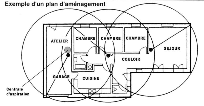
Inlet position depends on the actual length of the hose used. On the plan, draw the coverage areas, then verify them physically in the building.
- Favor open areas, hallways, walls near doors, closets and stairwells.
- Allow for going around furniture: a hose does not work in a straight line.
- Avoid areas where the inlet would be blocked by a door, a fixed piece of furniture or an appliance.
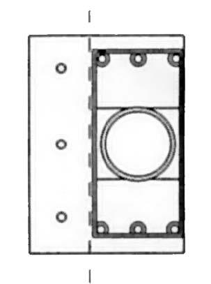
- For wall inlets, ensure correct orientation of the control contacts for the model used.
- Inlets can also be installed in the floor with the appropriate accessories.
Using a string or cord the length of the usable hose, start from each planned inlet and check the blind spots: behind doors, around islands, in bedroom corners, at the foot of stairs and in the garage.
Choose the network routing
Adapt the installation to the construction type.
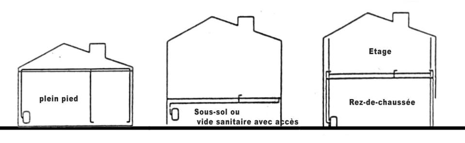
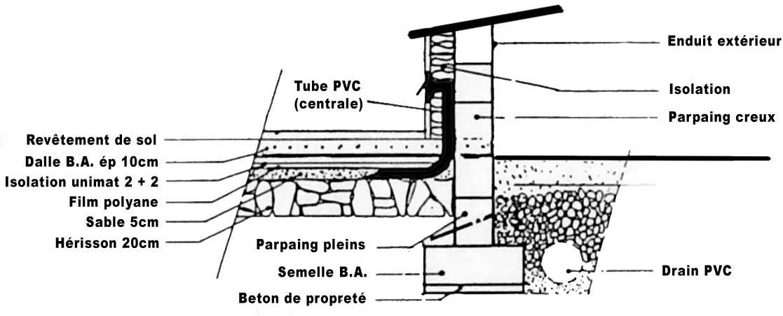
Lay the network in a sand bed after compaction. Protect the conduits against shovel impacts and later work with a suitable sleeve or mechanical protection.
Lay the conduits before the floor is closed. Protect and mark the tubes that protrude from the slab.
Installation can be done after the slab, keeping regular fixings and a direct route.
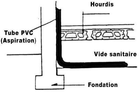
The exposed network can be fixed under the slab. Upper floors can be reached via a closet, technical duct, double partition or dedicated cut-out.
Where the job site allows, install the vacuum network ideally after the main plumbing runs and before closing up wall linings and certain electrical work.
Route the network
A direct main line, short branches.
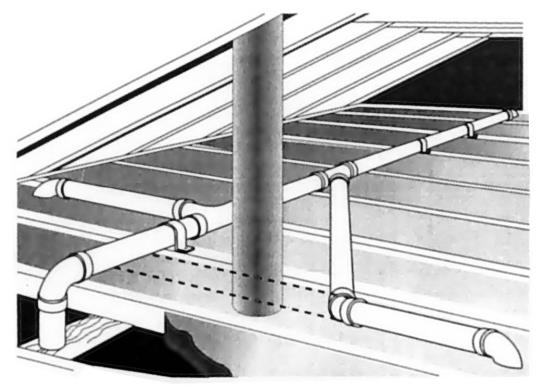
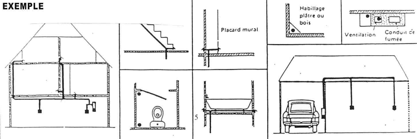
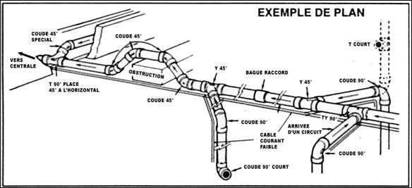
The main line connects the farthest inlet to the central unit. Other inlets join this line through branches. The network should stay as direct as possible, with as few unnecessary direction changes as possible.
Generally usable paths
- Underside of the slab in a basement or garage.
- Wall closet or walk-in closet.
- Dedicated technical duct or existing technical passage.
- Double partition or wall lining, with sufficient clearance.
- Riser to the attic then redistribution to the floors, where the building allows it.
- Disused conduit only after checking its use, condition and applicable rules.
Reduce pressure loss and the risk of clogging: a short network, suitable fittings, correct suction direction, and a clean tube interior.
Choose the fittings and the right direction
Matching diameter is not enough — geometry matters.
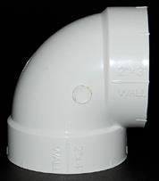
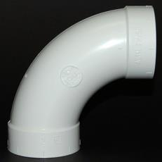
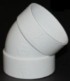
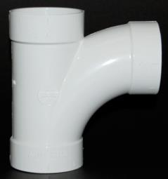
A poorly chosen fitting can create a turbulence zone, catch an object or cause a clog. The rules below are critical for network reliability.
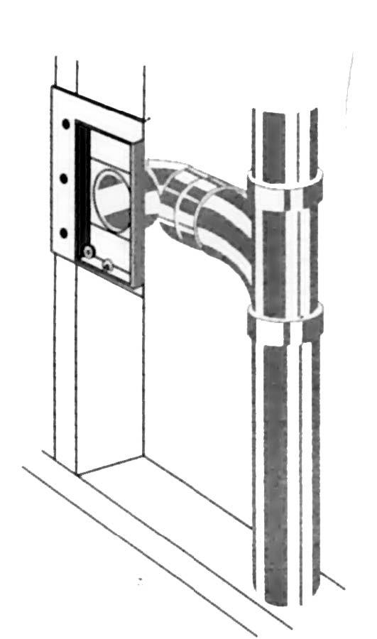
Only behind a traditional inlet: it also acts as a guard against objects that are too long.
Use in the network when the direction must change by 90°.
Preferred wherever the route allows, to soften direction changes.
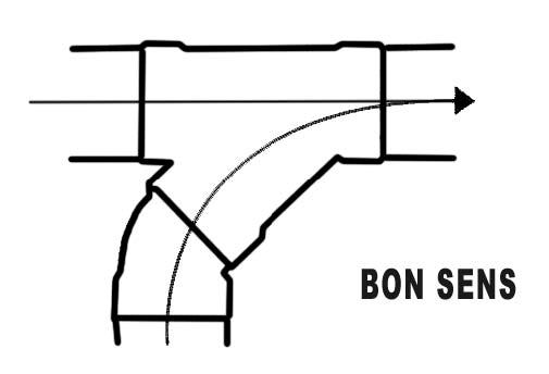
Always oriented in the direction of airflow toward the central unit.
Air must enter a branch without hitting a wall or having to double back. Orient the branch of the T/Y fitting toward the central unit.
Avoid gravity drops
A poorly connected downward branch can fill up with no suction.
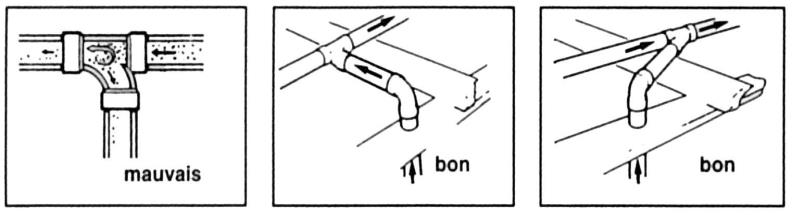
When an inlet's branch drops vertically below a main line, debris can fall by gravity into that branch while it is not in use. It may stay there until that inlet is next used.
Correction principle
- Do not create a vertical branch directly below the main line.
- Take the branch off to the side or above the main line, depending on the layout.
- Use the correct direction of the T/Y fitting and keep a connection slope that avoids the free fall of debris.
- Check the airflow direction before final gluing.
A properly made branch keeps debris from "falling" into an inlet that is not drawing suction.
Cut, prepare and glue
Airtightness is won through preparation, not glue quantity.
Measurements are taken to the inner stops of the fittings. Prepare the parts before gluing and do a dry fit to check the geometry.
Avoid glue drips and beads inside the conduits. A ridge of excess glue can catch fibers, hair and small objects.
Install the back-boxes
The finished position must be planned before plastering.
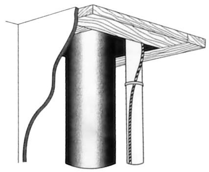
A wall back-box fitted with its short 90° elbow needs sufficient depth. The original manual states a need of about 10 cm for this setup. In a closet, the conduit can remain exposed inside while the back-box sits in the wall.
Height and comfort
For comfortable use, inlets are often placed at a height close to that of light switches, unless the project or a floor inlet requires otherwise.
Reference to the finished surface
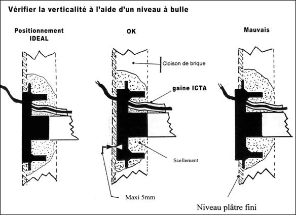
The face of the back-box must be positioned relative to the finished surface, not the bare wall.
A back-box set too deep makes fitting the inlet more difficult and can compromise airtightness.
Checks before closing up
- Check verticality with a level.
- Fix the back-box securely: it must not move during plastering.
- Keep access to the low-voltage wire and leave enough length.
- Temporarily plug the conduit to keep out construction dust and debris.
- Photograph the exact position before closing up the wall.
- In an exposed network, use a service inlet or a fitting suited to the type of conduit.
Leave about 20 cm of wire available outside the back-box so the inlet can be connected after finishing work.
Test wire continuity and photograph the position of the back-box and the tube run.
Wire the 24 V low-voltage control
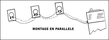
All inlets are wired in parallel.
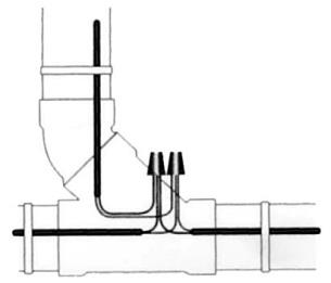
The control wire can run alongside the PVC network or follow a more direct path. The essential point is circuit continuity between all inlets and the central unit.
Installation rules
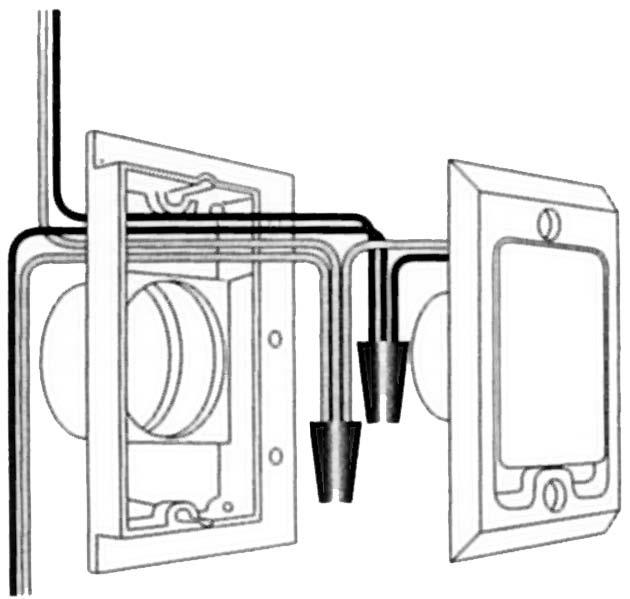
- Wire the inlets in parallel.
- Avoid more than two wires under the same inlet terminal: use an accessible junction box if needed.
- No connection should become inaccessible inside a slab or a closed wall.
- Do not run the wire through door openings.
- In masonry crossings and recessed areas, protect the wire inside a 16 mm ITCA conduit.
- Leave about 20 cm of slack at each back-box.
The 24 V circuit is used to trigger the central unit's start-up. The central unit's mains power supply remains a separate circuit.
Fit the wall and floor inlets
Connect without gluing the inlet itself.
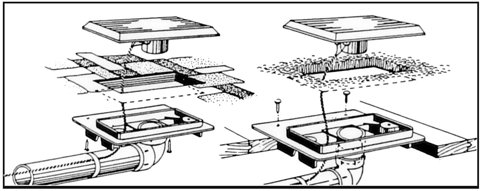
Wall inlet
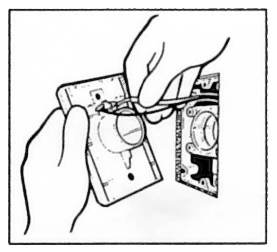
- Strip the low-voltage wire and connect it to the inlet's terminals.
- Lightly moisten the back-box gasket with water to ease insertion.
- Insert the inlet into the back-box without gluing it.
- Respect the orientation of the low-voltage contacts for the inlet model.
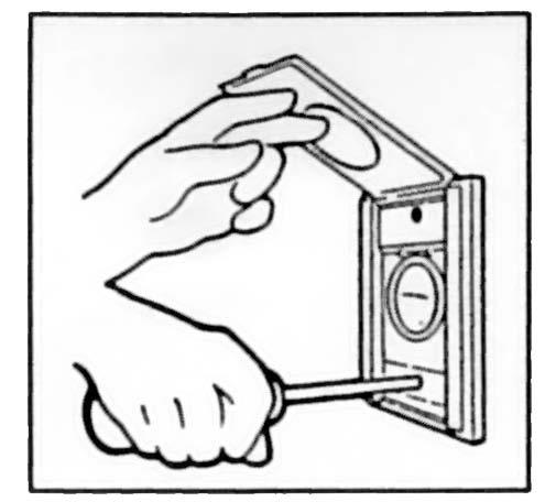
- Fix the inlet with the supplied screws and check that the faceplate sits flush against the finished wall.
Floor inlet
Use a back-box and an inlet designed for floor mounting. The faceplate must remain accessible and correctly positioned relative to the finished surface. Protect the mechanism during floor work.
Once fitted, a closed inlet must not let air in. A leak on a single inlet reduces the performance of the whole network.
Install the kitchen / toe-kick inlet
Sweep crumbs toward the inlet and trigger it with your foot.
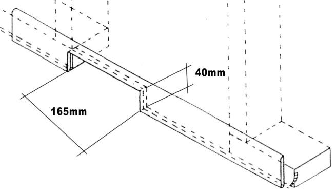
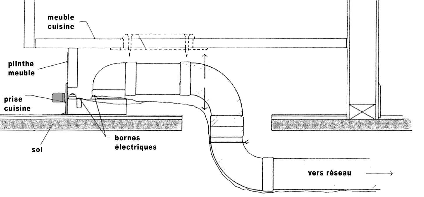
Choose a location under a kitchen cabinet or in an accessible toe-kick. Avoid areas taken up by the dishwasher, refrigerator or any appliance that would block access to the connection.
Dimensions from the original manual
The supplied Husky diagram calls for a toe-kick cut-out of 165 × 40 mm. Always check the exact template of the kitchen inlet supplied before cutting.
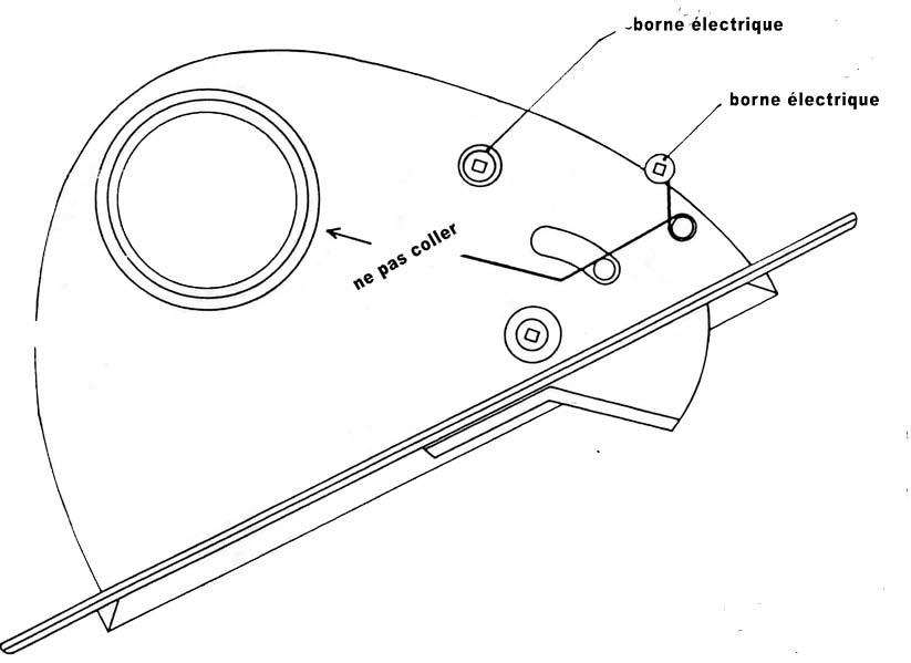
Connection
The connection to the network is made using the fittings intended for the model. Keep a smooth geometry and maintenance access wherever the layout allows.
Start-up
The kitchen inlet is generally triggered with the tip of the foot, via its built-in switch.
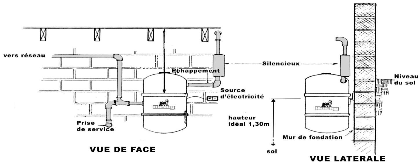
Mount the central unit
Accessible for maintenance, away from living areas.
The central unit can be placed in a garage, basement, laundry room or a dry technical room. The location must allow the canister to be opened or the bag changed, and give access to the filter, depending on the model.
Points to plan for
- A wall or support able to carry the weight of the central unit.
- Access to the canister, bag and filter without having to dismantle the network.
- A power supply matching the model's requirements; the original manual specifies an independent 16 A circuit for the models concerned.
- A flexible connector or coupling sleeve between the network and the central unit, to ease removal and limit vibration transmission.
- Silencer and air exhaust, depending on the central unit model and its manual.
- Enough space around the unit for ventilation and servicing.
The original Husky manual gives a height of about 1.30 m from the floor to the mounting bracket. Adjust it to the model and to emptying ergonomics.
Some central units are designed to work without an outside exhaust, others require or recommend one. Follow the manual for the installed model.
Connect and commission
Test every inlet before considering the job finished.
Once the PVC network, inlets and low-voltage wiring are complete, connect the central unit according to its manual. For standard low-voltage control terminals, the order of the two wires does not matter; still check the diagram for the installed model.
While the network is still accessible, an airtightness and operation test is far easier to correct than after plastering and finishing.
Use and maintain
The network lasts, provided the central unit's limits are respected.
Good practices
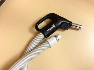
- Handle the hose with care and avoid knocks to the handle and contacts.
- Use the accessory suited to the type of floor or surface.
- Empty the canister or replace the bag according to usage frequency and the central unit's guidance.
- Clean or replace the filter only as directed by the model's manual.
- Do not vacuum water with a dust-only central unit.
- Do not vacuum long or rigid objects that could jam in the network.
- If power drops suddenly, stop and diagnose rather than force it.
Vacuuming water is only allowed if the central unit and installation are explicitly designed for that use. Otherwise: do not vacuum water.
Most problems come from a full bag or clogged filter, a poorly closed inlet, a leak at a fitting, or an object stuck in a poor-radius section.

Diagnose and inspect
Start with the simple causes, then isolate the area.
Quick diagnosis
| Symptom | Priority checks |
|---|---|
| The central unit does not start on any inlet | Mains power; circuit breaker; power outlet; connection of the two control wires to the central unit; contact test on the terminals per the model's manual. |
| A single inlet does not start | Inlet contacts; loose wires; wire cut between this inlet and the last accessible branch; inlet mechanism. |
| Weak suction everywhere | Full bag or canister; clogged filter; an inlet left open; a significant leak; obstruction near the central unit or on the main line. |
| Weak suction in one area | Obstruction or leak on the branch concerned; gravity drop; badly oriented fitting; stuck object. |
| Constant whistling | Inlet not closing properly; displaced gasket; non-airtight fitting; kitchen inlet not closing properly. |
| Abnormal noise or vibration | Central unit fixing; connecting sleeve; object in the turbine or canister; silencer or exhaust, depending on the model. |
Compare an inlet that works well with one that works poorly. This often reveals whether the fault is general or limited to one branch.
End-of-job checklist
- All inlets actually cover the planned areas.
- Short 90° elbows are used only behind traditional inlets.
- T/Y fittings are oriented in the direction of suction.
- No downward branch traps debris by gravity.
- All tubes were cut straight, deburred and chamfered.
- Glued joints are clean and no significant drips are visible inside.
- Back-boxes are at the correct level relative to the finished surface.
- The 24 V wire is protected in masonry areas and connections remain accessible.
- Every inlet starts and stops the central unit correctly.
- No closed inlet whistles, and power is consistent across the whole network.
- The central unit remains accessible for maintenance.
- The customer keeps the specific manual for their central unit and this network guide.
— Consult online
The complete guide, on screen.
Browse all 20 pages directly in your browser, or download the PDF to take onto the job site.
Document not displaying? Open the guide in a new tab.
— Download
Everything you need to install it.
Complete installation guide for the AspiWall / Husky traditional network: installation diagrams, choice of fittings and correct direction, back-box installation, 24 V low-voltage wiring, commissioning and diagnostics. Document in French.
Need a technical inspection?
AspiWall supports you in designing a new network, inspecting an existing installation, or troubleshooting a central vacuum system.